91-93 US VR4/91-98GTO Version 2 Plug and Play Flash Ecu Installation

91-93 US VR4/91-98 GTO Sticker
Thank you for purchasing a Jesters Plug and Play Flash Ecu. This ecu can be utilized for the following 91-93US VR4/91-98GTO depending on internal jumper setup. Please double check you are using the correct instructions for your application.
Installation Instructions 91-93 US 3000GT VR4/91-94 GTO
Package Content:
1x 91-93 3000gt VR4 US Spec/91-98 GTO Plug and Play (PNP) Flash Ecu with the latest version of Chrome preinstalled
1x OBD1-OBD2 adapter plug with flash plug for Tactrix 2.0 cable
1x 91-93 US VR4/91-98 GTO Plug and Play (PNP) Flash Ecu with the latest version of Chrome preinstalled
1x 91-93 OBD1-OBD2 adapter plug with flash plug for Tactrix 2.0 cable
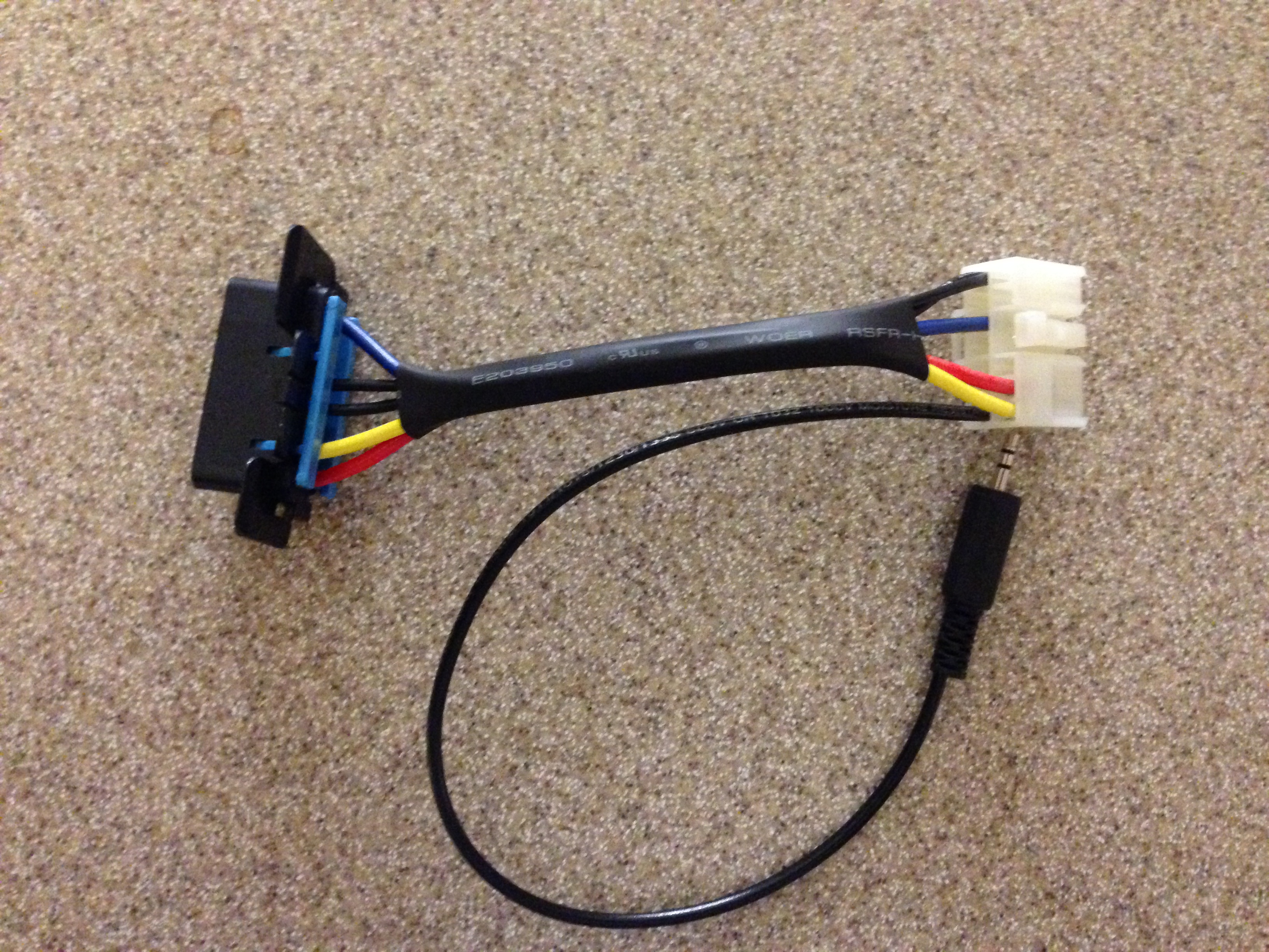
OBD1-OBD2 Adapter
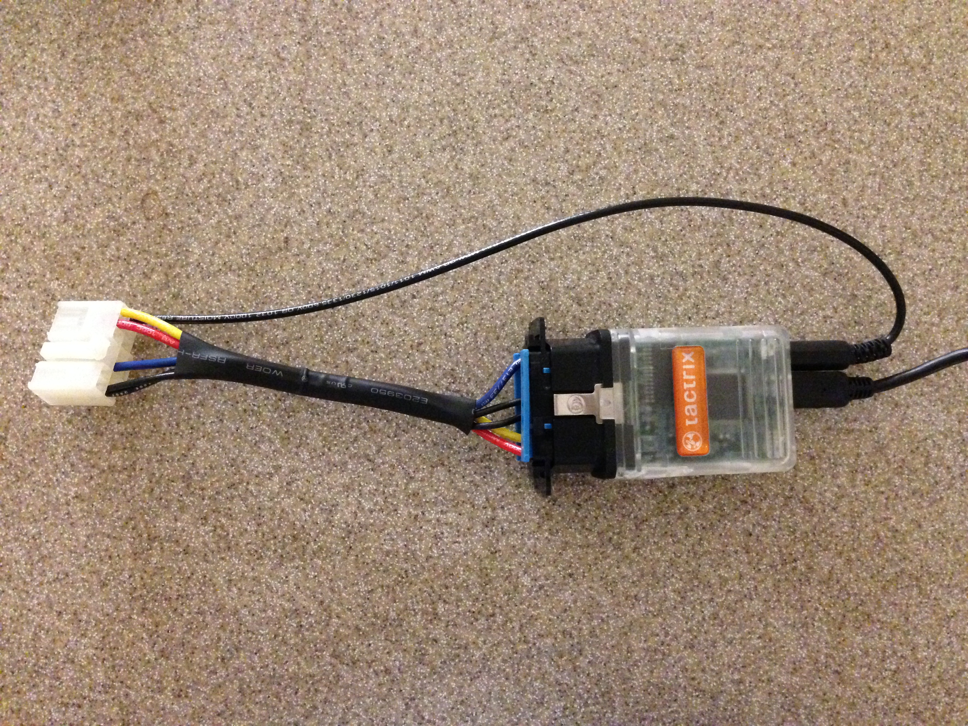
OBD1-OBD2 Adapter install on Tactrix 2.0
1x Gray 12pin connector with yellow and red wires
5x Extra ecu pins
1x Copy of Chrome – Free download via www.Chromedecu.com
Note: For 95-98 GTO installations the white 2G flash plug with yellow wire will be used instead of the obd1-obd2 adapter.
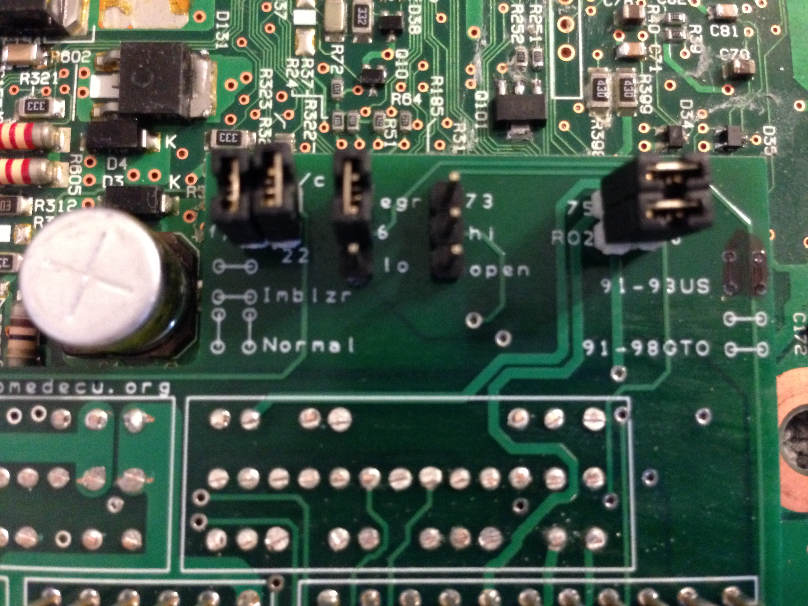
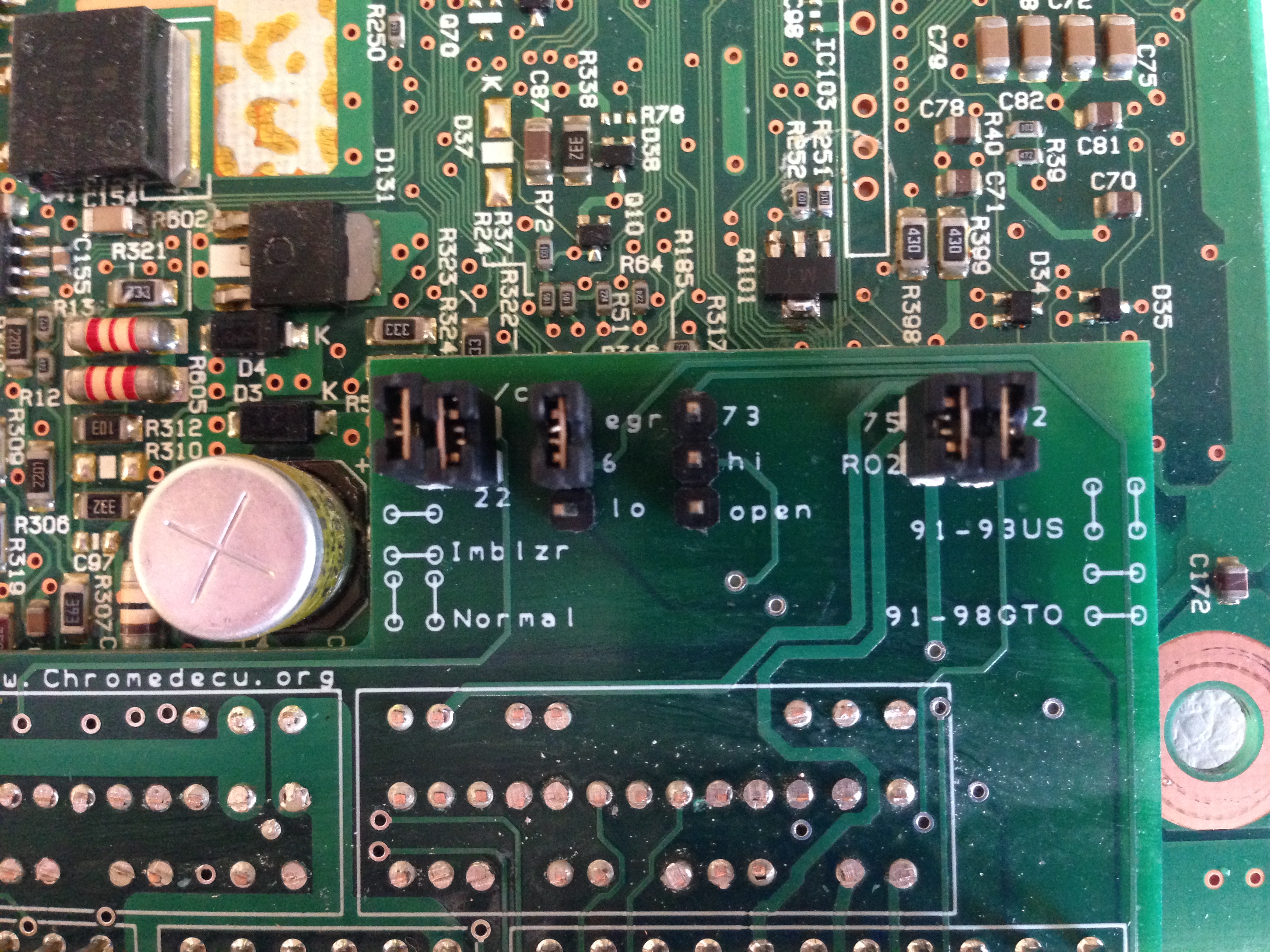
Jumper setup: The 91-93 US VR4/91-98 GTO PNP ECU jumper setup is pictured below. If your ecu jumpers do not look like the setup below double check your ecu version.
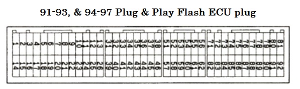
91-93 US VR4/91-98 GTO Pin setup
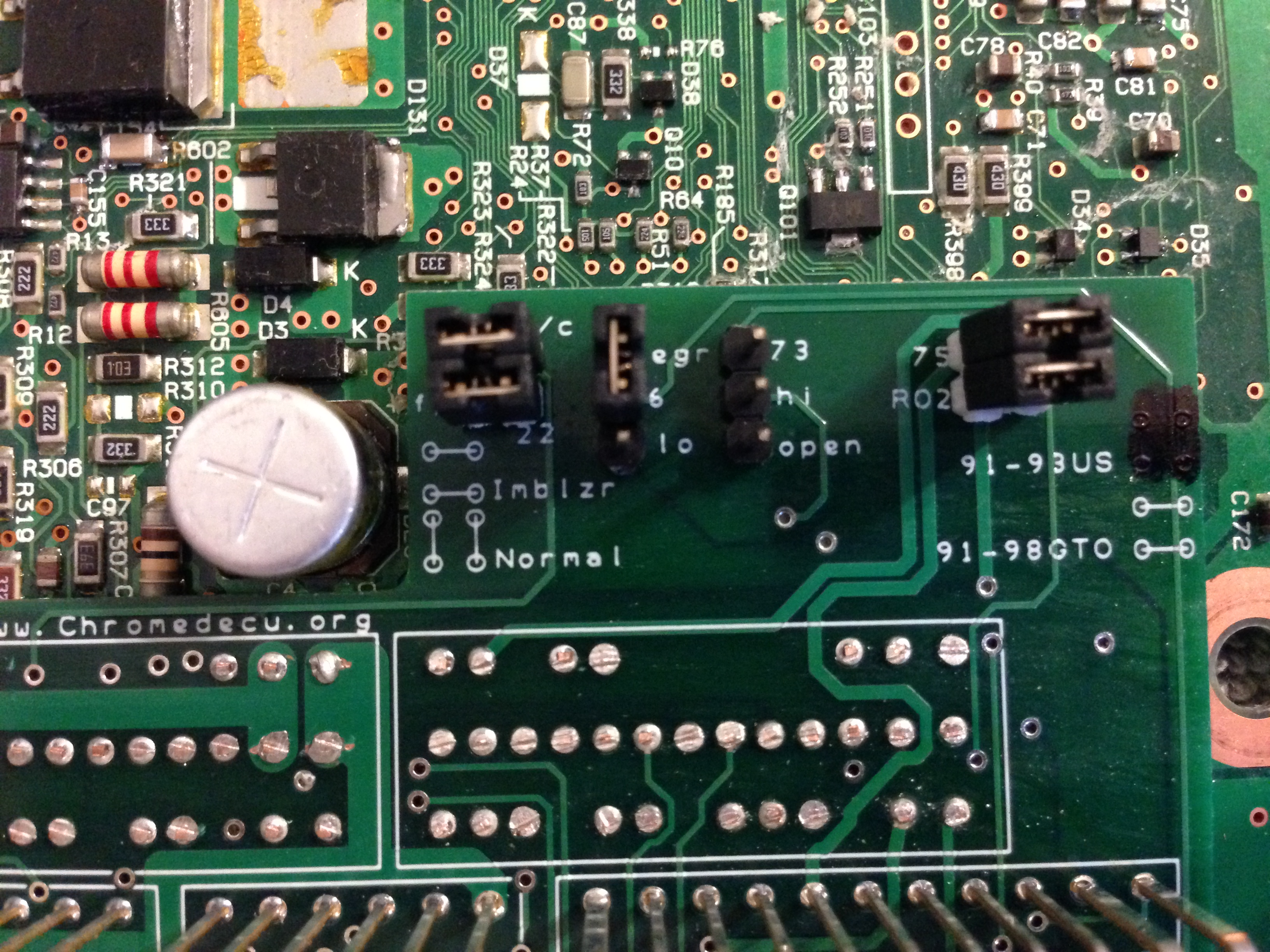
The primary O2 sensors can be switched by changing the jumpers. If the jumpers are turned 90 degrees this switches the primary O2 sensors. See pic below for switched O2 setup. Also note the white diagram to the right of the O2 jumpers have a misprint on the circuit board. The two vertical lines beside the 91-93 US should not be there. All 91-93US VR4 and 91-98 GTO have the same jumper setup as seen above. This misprint was found at post production inspection of the circuit board batch and all ecus were sent out with the correct jumper setup. The white lines are marked out with marker during ecu production as seen above, however some ecus have been sent out with out the lines marked out by marker.
91-93 US VR4/91-98 GTO
Pin Setup reverse O2s
For a GTO with an Immobilizer the following jumper setup is required.
Jumper setup for GTO with Immobilizer
Step 1- With car off, remove stock ecu(See A) from behind center console.
Step 2- Plug the 3 stock plugs and the supplied gray 12 pin plug with yellow and red wire into PNP ecu.
Step 3- Route the yellow & red wires to the stock OBD1 connector (See B) by the fuse box under the driver side dash.
Step 4- Plug the yellow wire into the back of the OBD1 connector, pin 6 (corner location).
Step 5- Plug the red wire in pin 2.
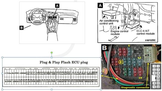
OBD1 setup
Your car is now converted to a Flash Ecu running Chrome. It is a full OBD2 ecu. You can now use any OBD2 reader or the Tactrix 2.0 cable to reflash or datalog your car when using the supplied adapter. The adapter does not have to be installed unless you are datalogging, reflashing or reading the OBD2 codes/data.
Installation Instructions 95-98 GTO
Note: For ‘95-’98 GTO installations a flash 2G flash plug is needed. Contact us via www.Chomredecu.org for 2G flash plug if needed.
Package Content:
1x 91-93 3000gt VR4 US Spec/91-98 GTO Plug and Play (PNP) Flash Ecu with the latest version of Chrome preinstalled
1x OBD1-OBD2 adapter plug with flash plug for Tactrix 2.0 cable (not used on 95-98 GTOs)
1x Gray 12pin connector with long (3ft) yellow and red wires installed.
1x White reflash connector with yellow short (1ft) wire installed (not used on 91-93 obd1 cars).
5x Extra ecu pins
1x Copy of Chrome – Free download via www.Chromedecu.com
Installation Instructions 95-98 GTO
Note: For 95-98 GTO installations the white 2G flash plug with yellow wire will be used instead of the obd1-obd2 adapter.
Jumper setup: The 91-93 US VR4 PNP ECU can reverse the primary O2 sensors by changing the jumpers.
Stock setup the jumpers should be horizontal with the plug down. If the jumpers are vertical this switches the O2s.
Step 1- With car off, remove stock ecu(See A) from behind center console.
Step 2- Remove long (3 ft) red and yellow wires from gray connector. Use a small paperclip inserted in front of connector to release pin.
Step 3- Install short (1ft) yellow wire that attaches to reflash connector in pin 51 of gray plug. Ensure pin seats to the front of the plug.
Step 4- Plug the 3 stock plugs and the supplied gray 12 pin plug with yellow wire into PNP ecu.
Step 5- Route the yellow wire and attach white flash plug to small bracket forward of the stock OBD2 plug. See B.
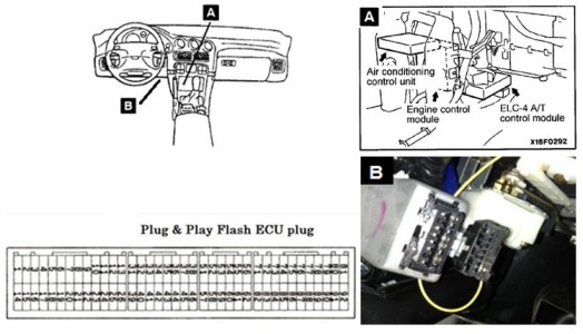
Obd2 setup
Your car is now converted to a Flash Ecu running Chrome. It is a full OBD2 ecu. You can use any OBD2 reader or the Tactrix 2.0 cable to reflash or datalog your car. The Tactrix supplied Mits reflash connector must be plug in to read or write(flash) a rom to your ecu. It does not need to be hooked up for datalogging or code reading.
| Pin Number 91-93 US VR4/91-98GTO/91-95 SL Fed Spec Version 3 Plug and Play Flash Ecu | Pin Number 98-99 | 98-99 VR4 Function |
| 74 | 92 | Map Sensor 0-5V |
| 51 | 100 | Reflash Connector |
| 52 | 17 | Fan Motor Relay (Hi) |
| 53 | 18 | Fan Motor Relay (Lo) |
| 54 | 35 | EVAP emission vent solenoid |
| 55 | 93 | WBO2 0-5V |
| 56 | NA | Obd1 Power 12V |
| 57 | 97 | Future Use |
| 60 | 96 | Future Use |
| 61 | 73 | O2 Sensor Rear Post Cat |
| 62 | 74 | O2 Sensor Front Post Cat |
| 91 | 67 | NLTS |
The plug views below is as if you were looking straight at the ecu plug or the back of the vehicle ecu plugs.