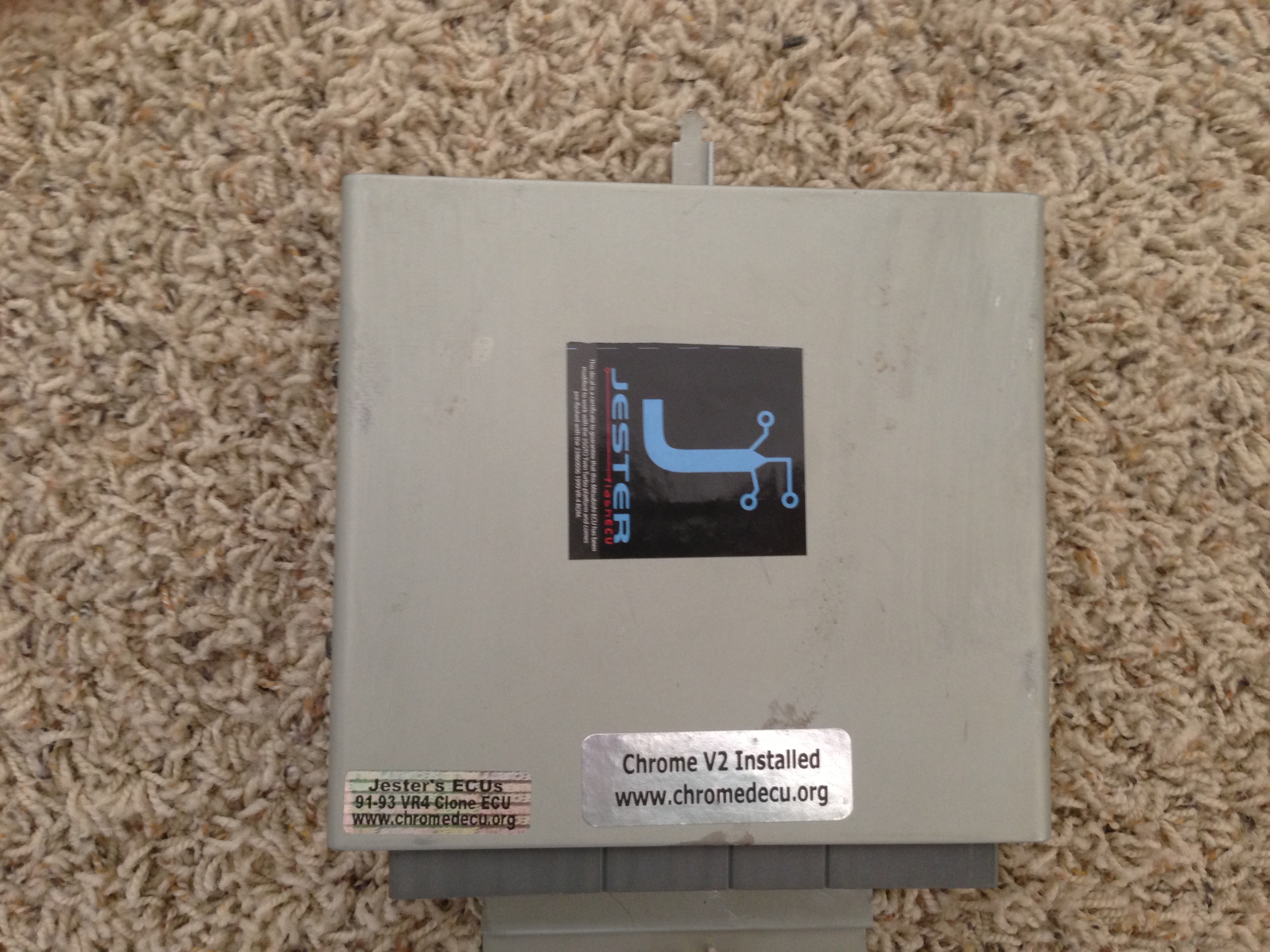
91-93 US VR4 Version 1 Plug and Play Flash Ecu
for Mitsubishi 3000gt VR4 or Dodge Stealth TT
Contents:
1x Plug and Play(PNP) Flash Ecu
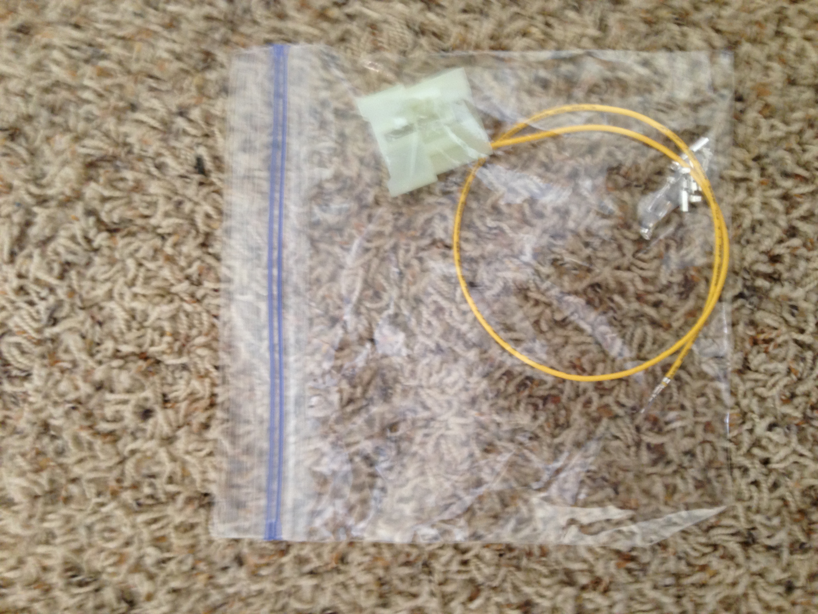
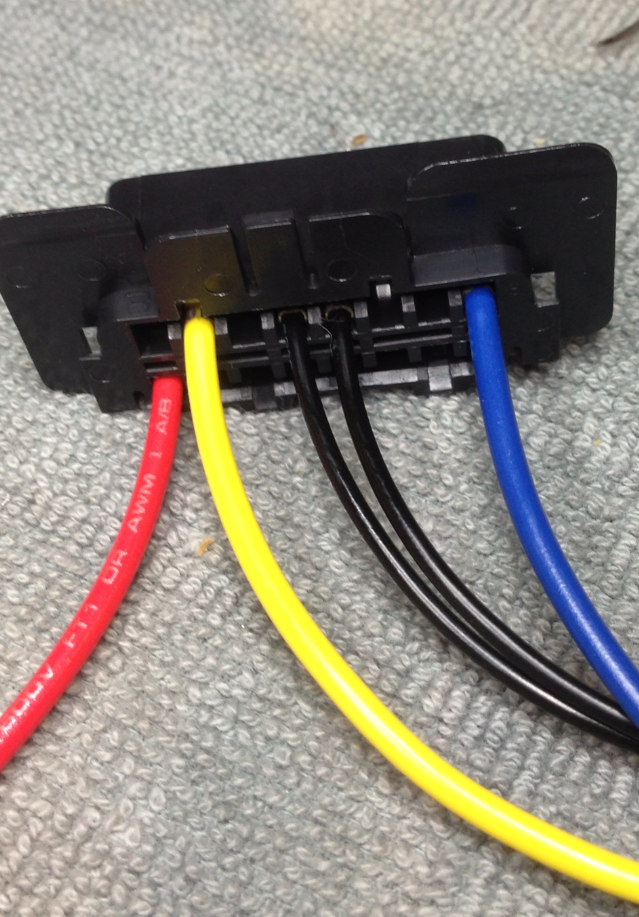
2x New Obd1 lead wires (one yellow and one red)
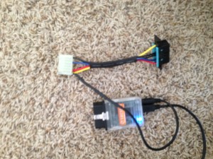
1x Obd1 to Obd2 adaptor for the Tactrix 2.0 cable
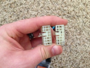
1x Gray 12 pin plug
5x new pins
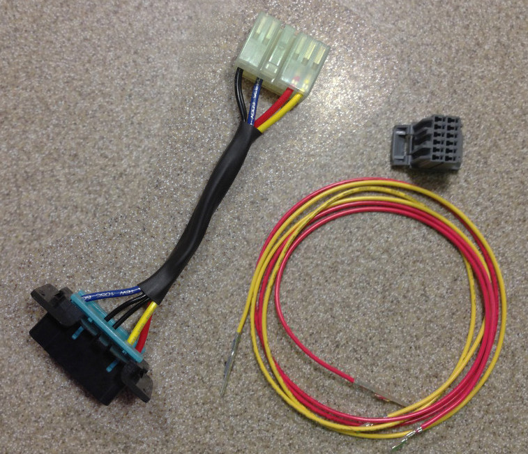
You get the obd1 adapter for your car, the 2 new lead wires(red and yellow) and the new grey 12 position plug with pins for all the extra pins the flash ecus offer.

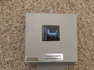
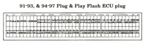
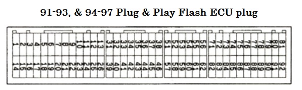
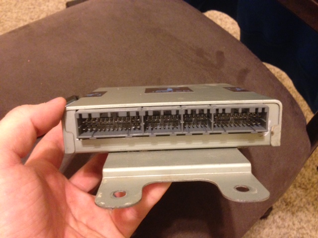
Stock 1G VR4 ecus have three plugs. There are 4 plugs on the 1G PNP Flash Ecu.
The 4th plug is a gray 12 position plug (included) for all the extras inputs and outputs the Flash ecu offers. You can just plug the stock three plugs in the PNP Flash Ecu and your car will start and run fine. To use the flash pin (51 on 91-93 PNP Flash Ecus), WBO2 logging, boost logging, ect. you will have to wire them up.
The obd1 flash adapter allows you to just plug one plug into your car to datalog and flash it. The 94-97 and 98-99 cars all have to plug in 2 plugs to flash their cars.
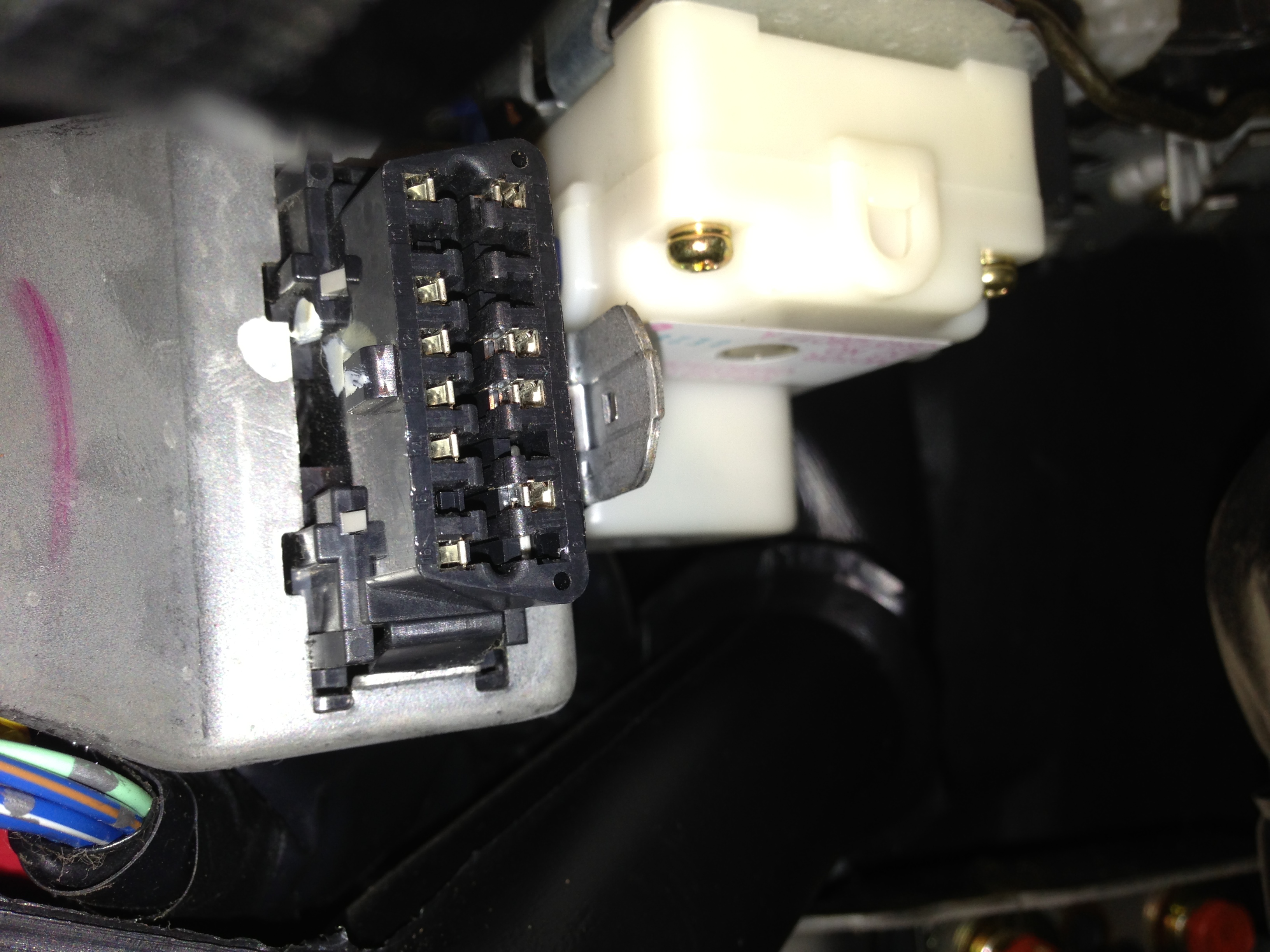
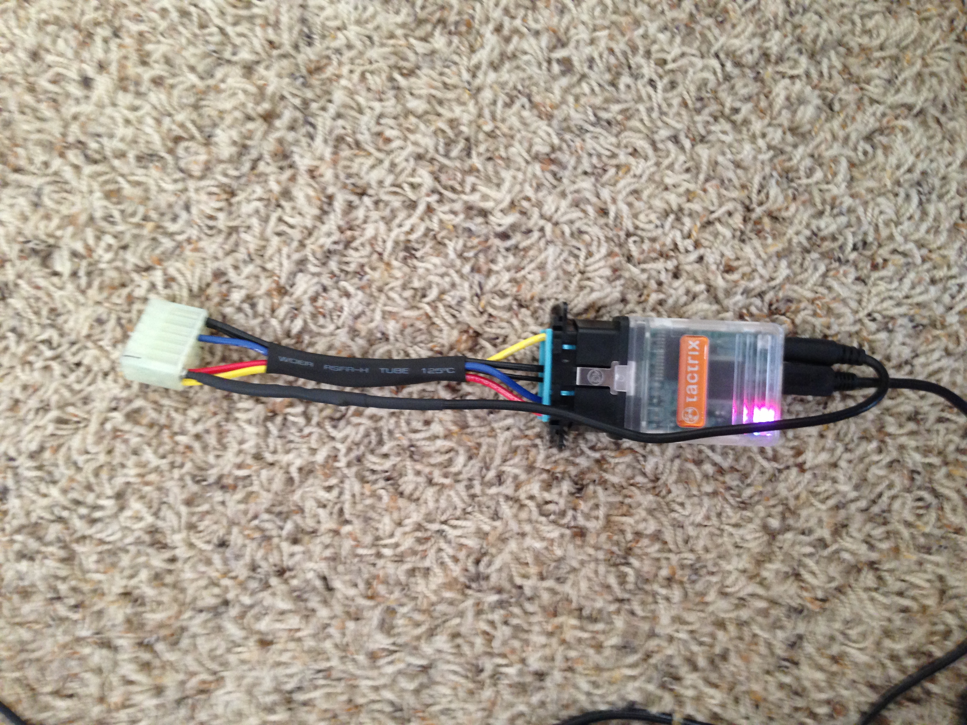
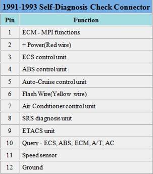
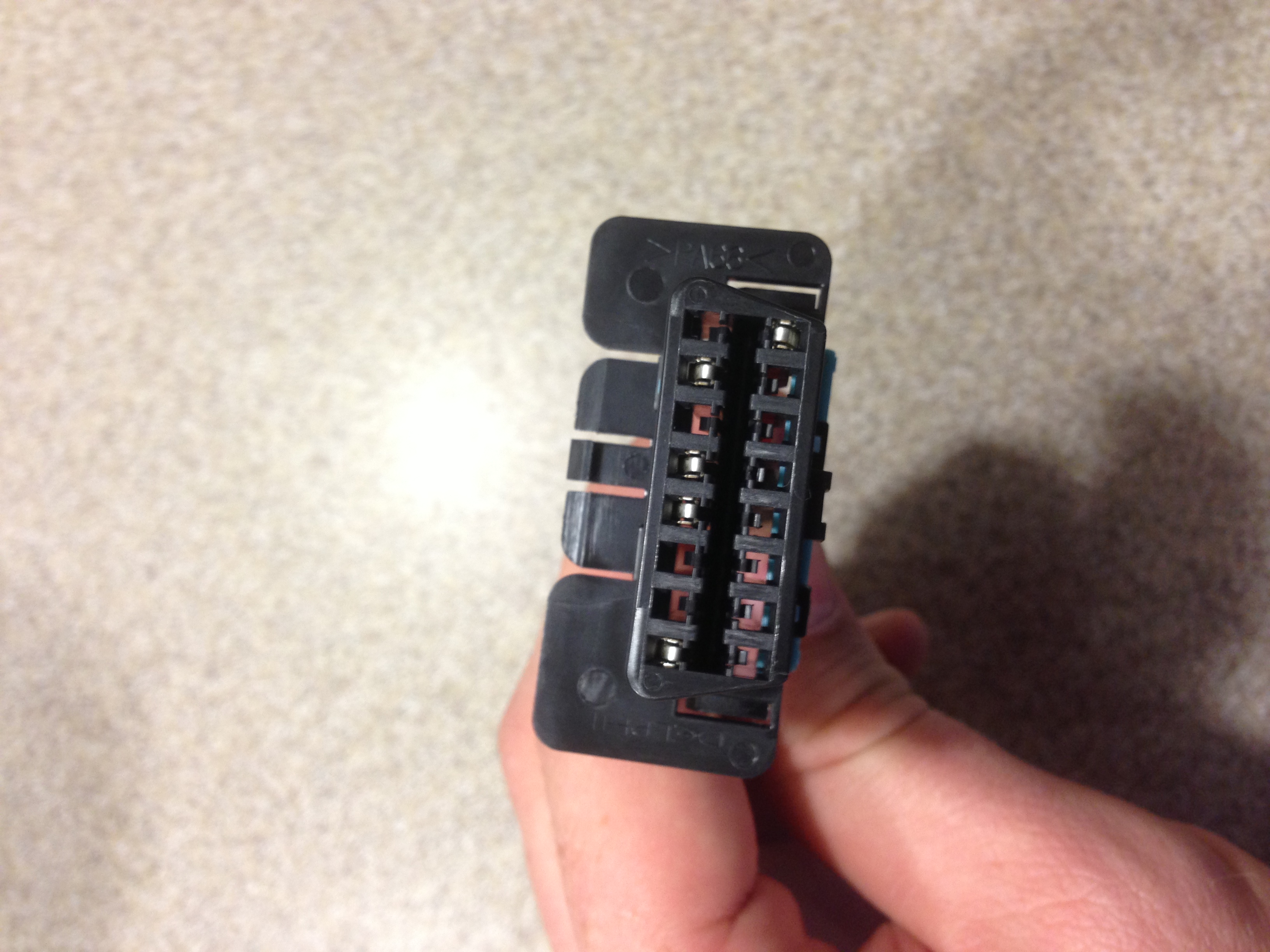
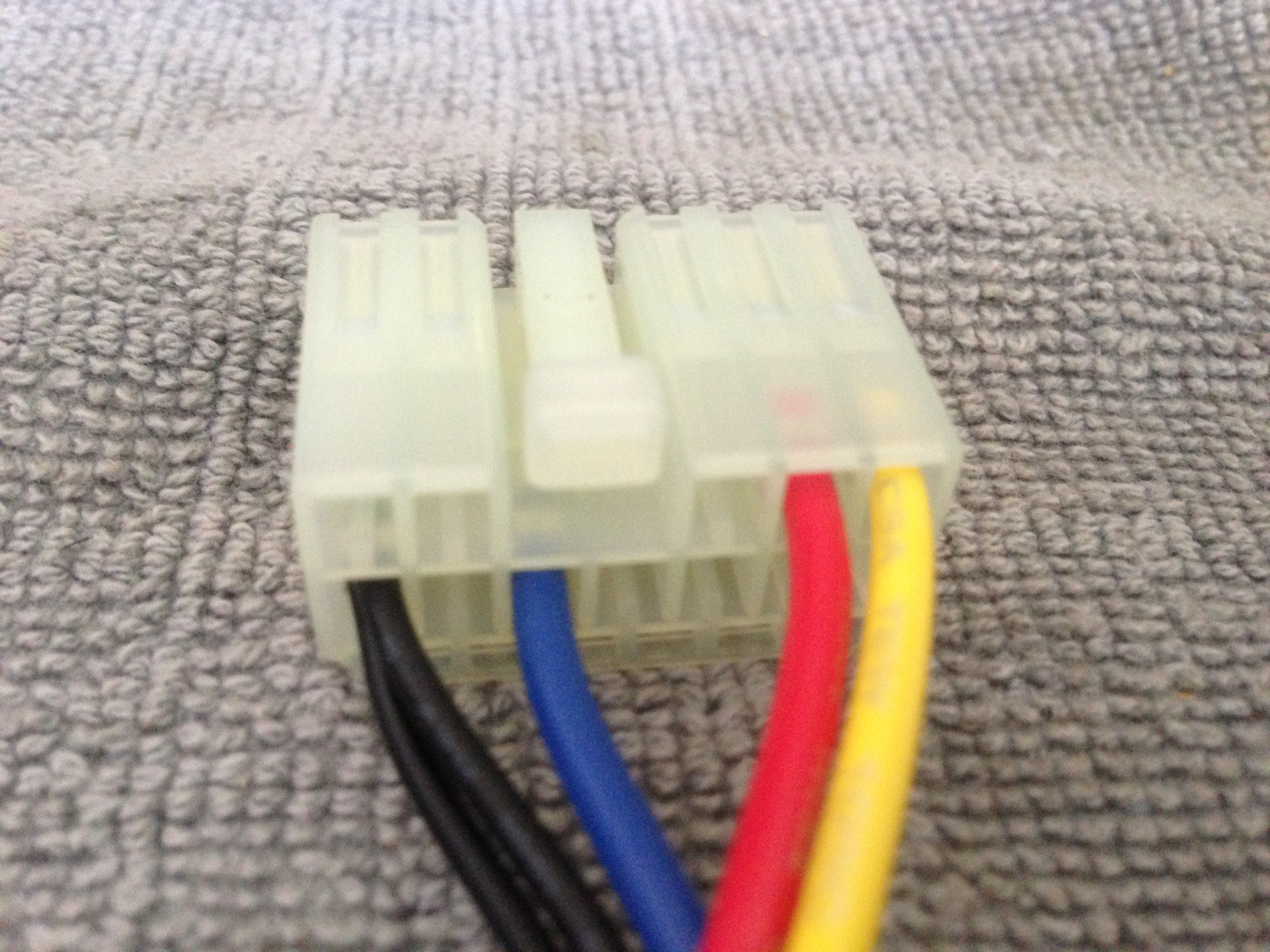
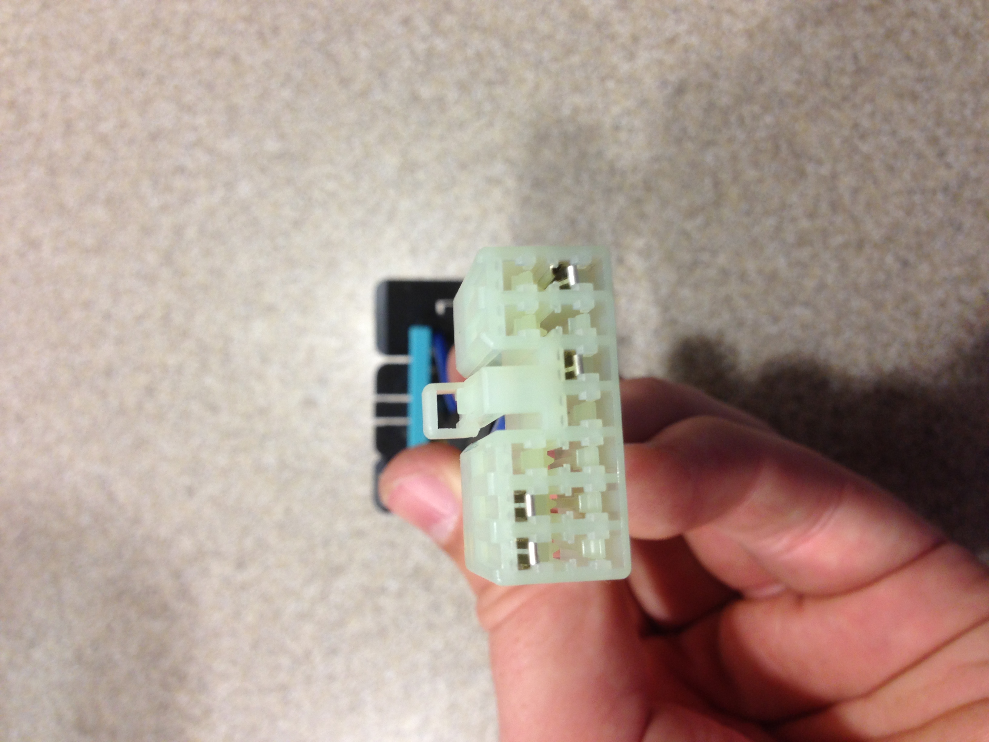
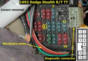
The mitsubishi reflash connector, that comes with the tactrix 2.0 cable, plugs into the obd1 on 91-93 VR4s. Its the same plug as the white one below.
You have to remove the pin in the reflash connector and put it in the same location in the obd1 plug of the adapter. Then you can plug it into your tactrix 2.0 cable and you are set. The adapter doesn’t need to be plugged in unless you are datalogging or flashing.
It stays with the tactrix 2.0 cable in your glove box most of the time.
Interesting fact: The 91-93 obd1 plug is the same plug used on the 98-99 3000gts for the flash connector. on the 98-99 VR4 it is located beside the obd2 plug.
I actually like this set up better than my 99 vr4 because I have to plug in the two plugs everytime. Its kind of annoying. I may wire it up like a 1g to use my adaptor on it. haha.

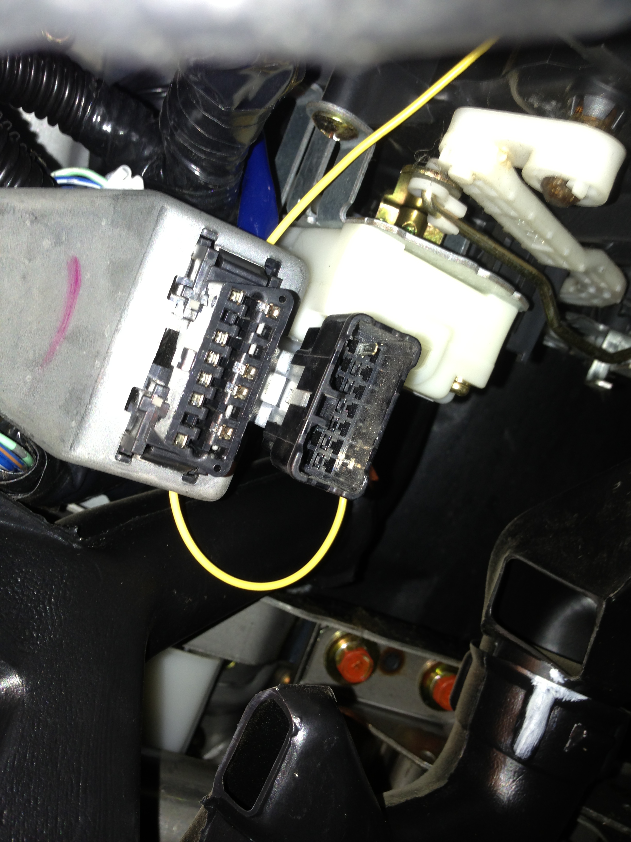
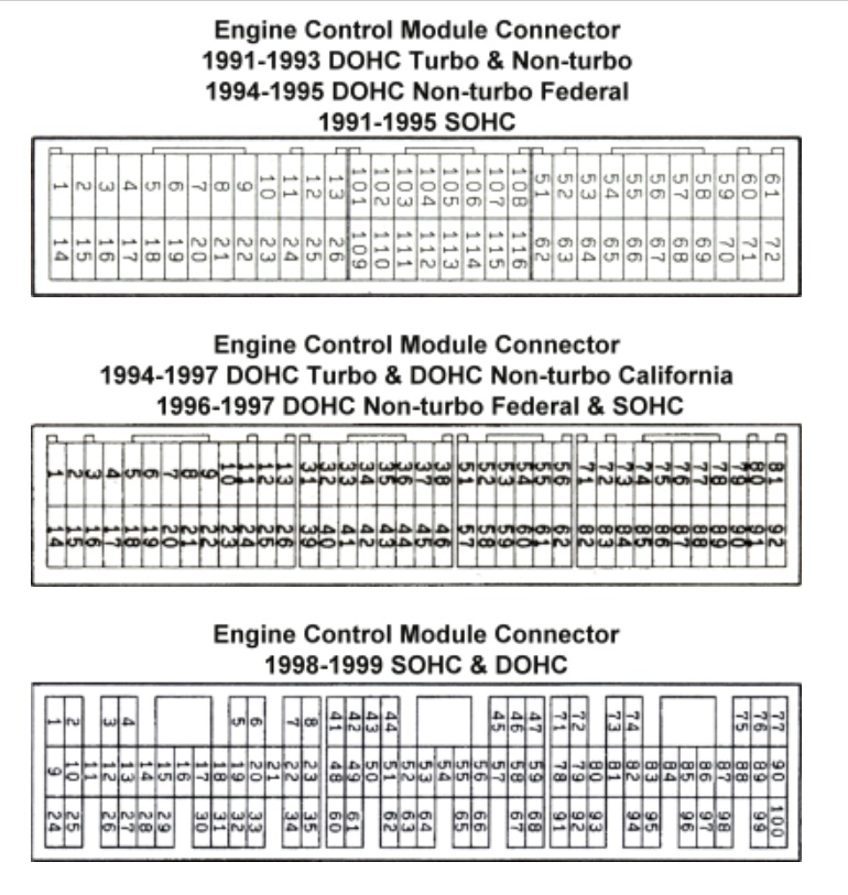
The long yellow wire is your flash wire and it plugs into the flash ecu pin 51 (see pin out below) and then into the back of your stock obd1 plug pin 6. The long red wire is your power wire and it plugs into the flash ecu pin 77 and then into the back of your stock obd1 plug pin 2. Don’t mix the wires up.
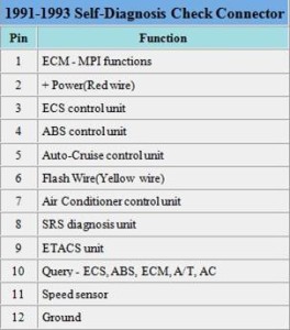
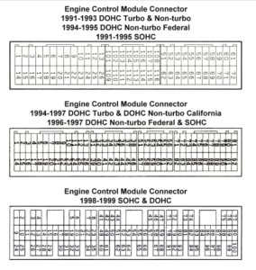
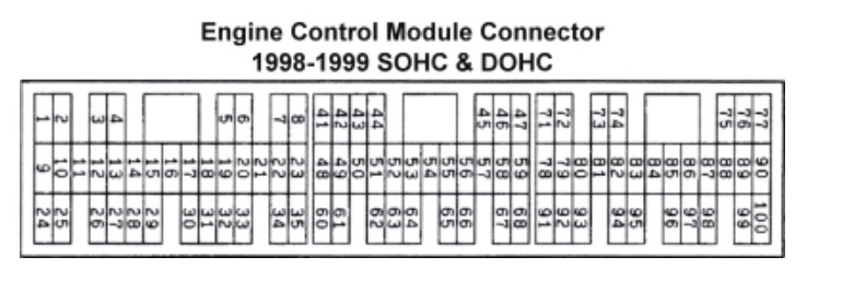
The plug views below is as if you were looking straight at the ecu plug or the back of the vehicle ecu plugs.